0 10v Dimming Ballast Wiring Diagram
Low Voltage Led 0 10v Dimming Usai

Cw 5531 Lutron Led Dimmer Switch Wiring Diagram Download Diagram

Oe 5906 Halo Light Wiring Diagram Also Lutron Grafik Eye Wiring

Hd 1337 Leviton 0 10v Led Dimmer Wiring Diagram Free Diagram
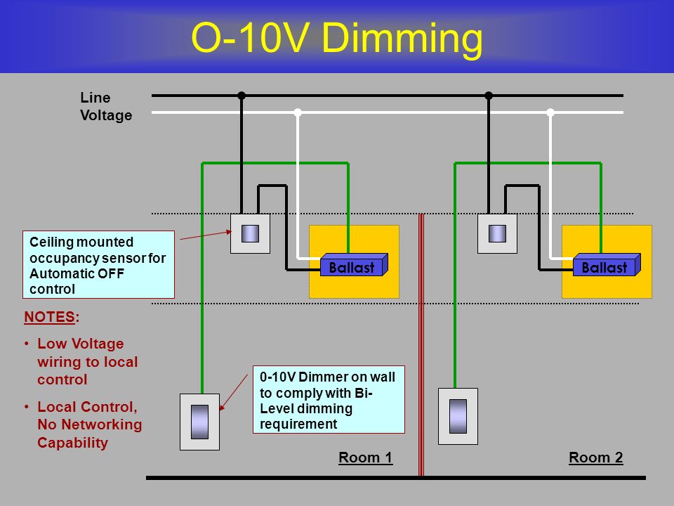
Brian Liebel Pe Lc Afterimage S P A C E Ppt Download

Advance Mark 7 Wiring Diagram Tukir Www Tintenglueck De

Our standard 0 10v dimming driver option is often provided standard check spec sheets and dims down to 10 at minimum light level.
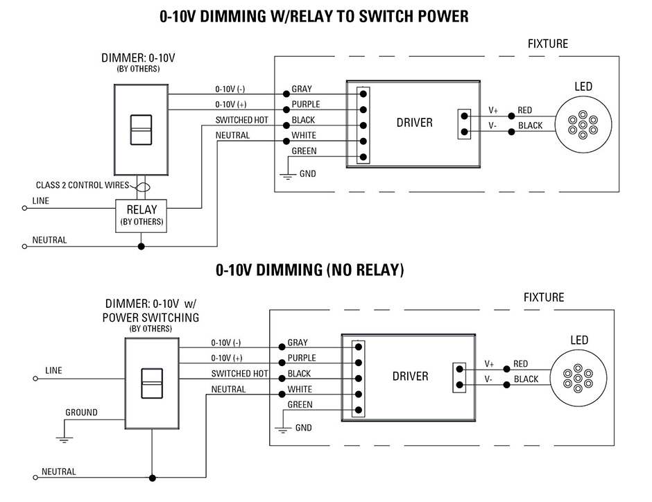
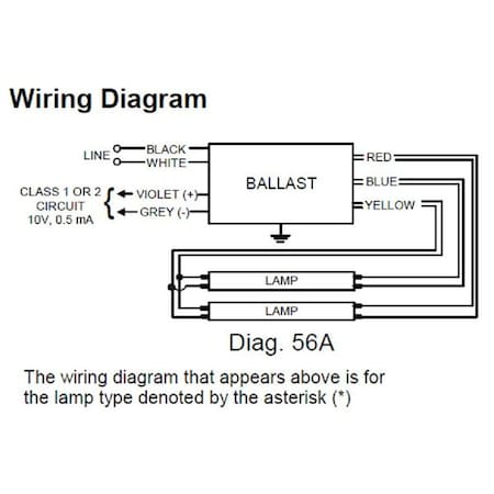
0 10v dimming ballast wiring diagram. A wiring diagram is a type of schematic which makes use of abstract photographic symbols to reveal all the affiliations of components in a system. A typical 0 10v wiring diagram is shown below. A philips advance mk 7 ballast izt 2s32 sc ballast install is shown here. 0 10 v ballast driver dimming with on off control wiring diagram using relay figure c1.
A wiring diagram is a simplified standard photographic depiction of an electric circuit. 0 10v dimming ballast wiring diagram collection slerhfaceitsalon. If the light output can only be dimmed from down to 10 there must be a switch or relay available to kill power to the system and turn the light. Dimming with on off control via relay connect the control as shown in figure c2.
A wiring diagram is a streamlined standard photographic representation of an electric circuit. 0 10 v ballast driver white. It shows the elements of the circuit as simplified shapes and also the power and also signal connections in between the devices. This is a 120v or 277 volt ballast 4435 290 32651 rev.
C similar to any other 0 to 10 volt dimming driver or ballast. It shows the elements of the circuit as streamlined forms and the power and signal connections between the devices. Refer to the wiring sheet included with the relay for more information. It is the default.
Collection of 0 10 volt dimming wiring diagram. 0 10v dimming ballast wiring diagram just what s wiring diagram. Variety of 0 10v dimming ballast wiring diagram.
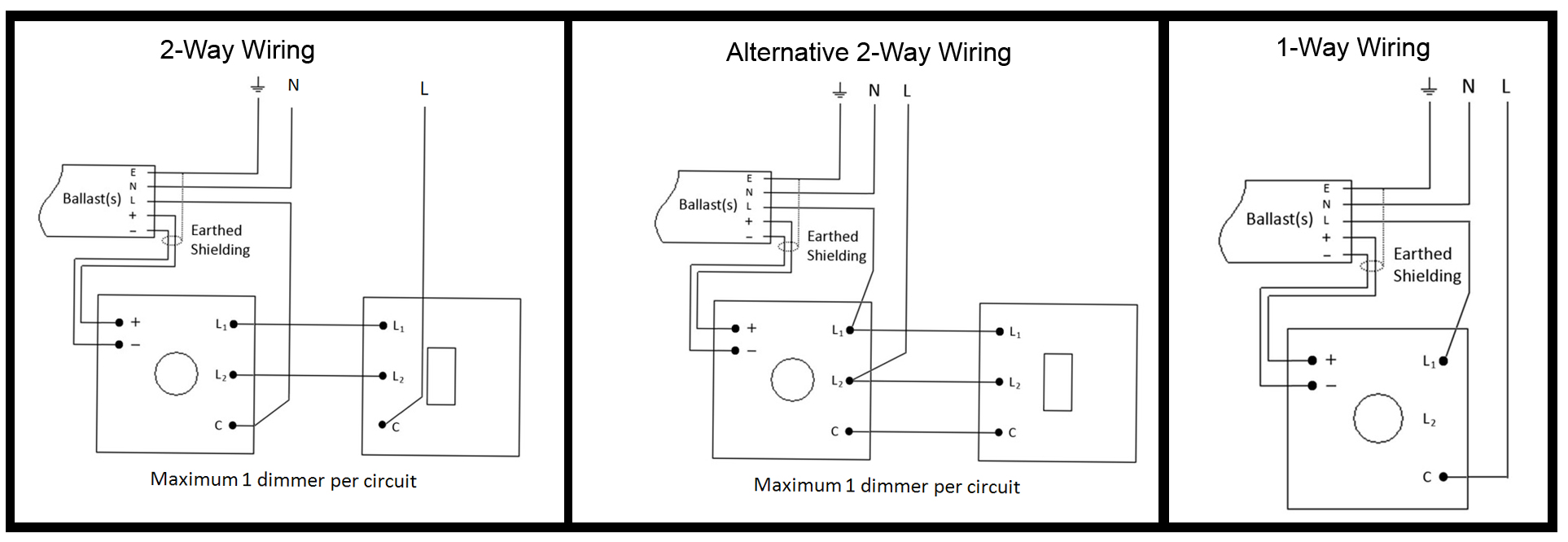
Varilight Specialist Modules

Hm 1198 Wiring Diagram For Led Downlights Schematic Wiring
Cw 5531 Lutron Led Dimmer Switch Wiring Diagram Download Diagram

Unilight Electric Halo Recessed Lighting 0 10v Led Dimming Info

Emergency Lighting With Dimming Control Functional Devices Inc

D375c Dimmable Led Driver Wiring Diagram Wiring Resources
Philips Advance Izt 2s28 D 85 84 Dimming Ballast Electronic 120

Ym 1045 Motion Sensor Light Switch Wiring Diagram Lutron 3 Way
